

Planning the Conversion
The first thing to do was to find a suitable CMOS camera. A cooled model was ruled out, since from its place inside the camera, it would have heated up the tube interior. Moreover, it would have been too heavy for the old spider to carry. Soon, it became clear that the ZWO ASI294MC was the model having the biggest chip, whose size best fitted the tube and whose technical characteristics promised good results. Even at a temperature above +20°C, this detector produces very low thermal noise, during in color imaging. Its pixel size of 4.63 µm is close to the resolution limit of the Schmidt design even in the corners of the detector. The 4144 x 2822 pixels suggested an image diagonal of more than 4.5° on the sky.
Flattening the field was the biggest demand. Roger Ceragioli produced a solution, by designing a field flattener in the ray-tracing program ZEMAX. The solution resulted in a plano-convex lens of 25 mm dia. and 200 mm focal length, with anti-reflection coatings. Also, the Schmidt’s corrector plate had to be moved a few centimeters closer to the mirror, which meant that the tube had to be shortened – i.e. the end had to be sawed off (see the table below for the final specifications).
The challenge in positioning the field flattener was that the slightest deviation from the design could lead to large aberrations in the images. Since my fine-motor skills are less than well-developed, after discussions with Walter Stephani and Roger Ceragioli, I made the mounting adjustable.
Executing the Changes
Celestron’s Schmidt cameras have as a special feature invar rods, which do not vary their length even with large temperature changes and so keep the film holder at a constant distance from the mirror. I know that this advantage absolutely had be maintained! To bring the CMOS detector to the focal plane, I had to extend the invar rods by 30 mm using hollow screw sleeves, because the detector’s surface (due to the height of the ZWO camera) had moved closer to the mirror (vis-à-vis the original film holder) by about 25 mm. The camera’s housing was attached via a helical extension mechanism at its rear to the existing film holder/spider of the Schmidt camera. In this way, the distance of the chip from focus could be altered and locked down to micron accuracy. An additional adjustment was provided by strong snap rings on the connector of the original film holder to the invar rods. This meant that the CMOS detector could be tilted very accurately via adjustment screws.
After close consultation, Walter Stephani and the author developed a means of mounting the combined UV/IR filter with the plano-convex corrector lens. The two were “fused” together using immersion oil to form (in effect) a single optical element. This had to be placed in the light path at the correct distance from the detector to an accuracy of 0.1 mm. Gerd Neumann Jr. of Hamburg manufactured the mount for this, which is firmly screwed to the camera body.
The last step of the conversion was effected by setting the new, shorter distance of the Schmidt plate. To this end, 58 mm of the aluminum tube was sawed off and the corrector plate was reattached.
Table of Optical Components and Distances
|
Designation |
Radius |
Distance |
Diameter |
|
Detector surface |
- |
0 mm |
23.2 mm |
|
Air gap |
- |
5.58 mm |
25.0 mm |
|
UV/IR filter |
- |
1 mm |
25.0 mm |
|
103.36 mm |
Oil-Spaced / |
25.0 mm |
|
|
Mirror |
609.6 mm |
292.8 mm |
223 mm |
|
Schmidt plate |
5.08 mm |
529.8 mm |
203 mm |

Test Phase
With the conversion complete, testing began. The first target was a daytime wind turbine. I could already find the overall focus position relatively well. But small errors, as expected, could be seen throughout the field: the left side was slightly sharper than the right, and the corners were not sharp. Further tests followed using a C8 as collimator.i Employing a special procedure I found on the Web (see the links below), the entire field could be adjusted and corrected. A crosshair eyepiece in the C8 was focused on infinity and directed to a bright background. The Schmidt camera now looked directly into the C8 and the crosshairs of the latter were imaged onto the CMOS detector. By positioning the crosshair first on the detector's center and then its four corners, image sharpness across the field could be accurately adjusted.
First Light
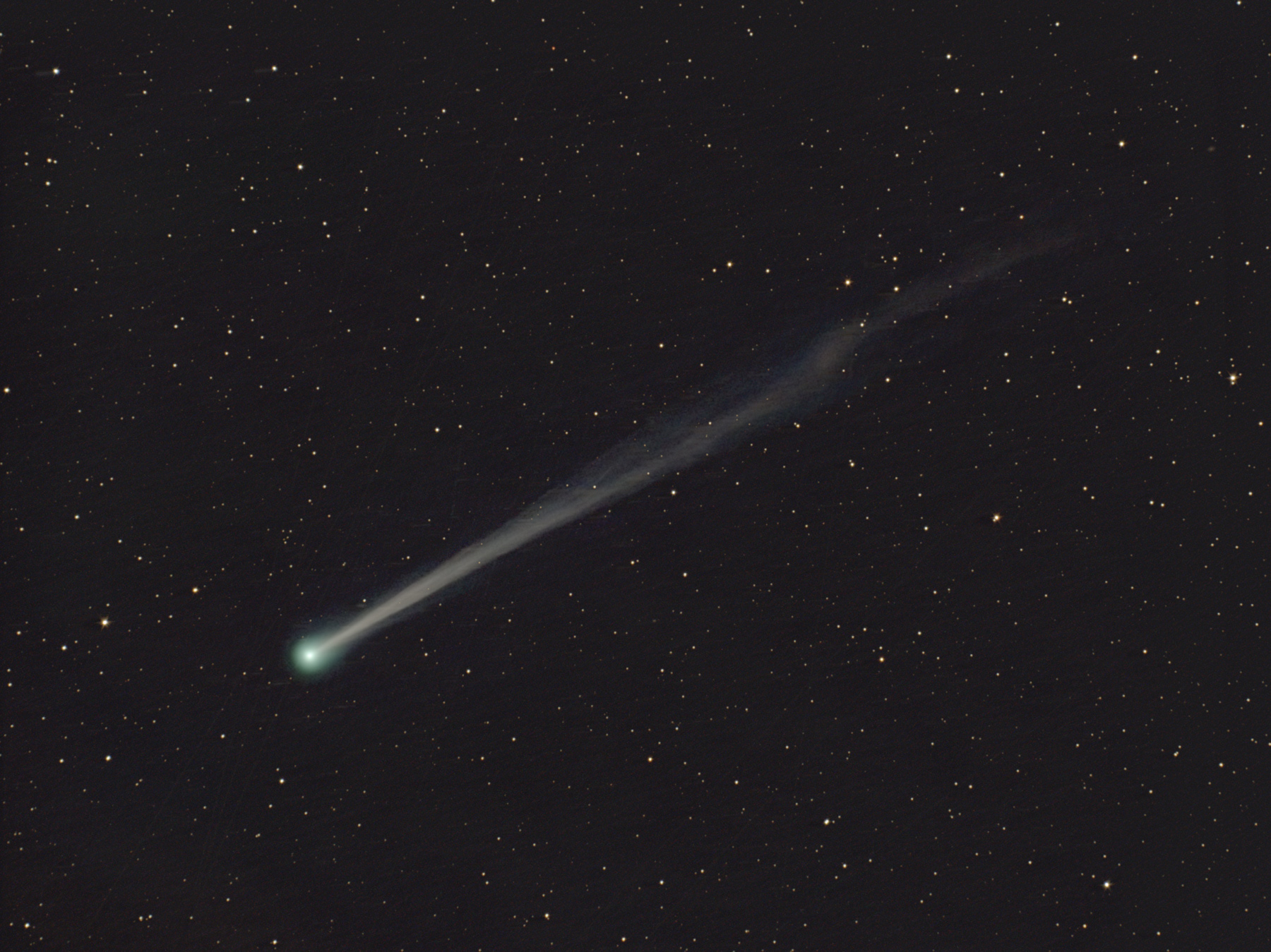
On the first clear night, the converted Schmidt camera was turned to the sky. The target selected was Comet C/2022 E3, near NGC 1647. There were many bright stars in a large field, in addition to the comet. Even the raw images (after a final adjustment) gave convincing proof: all the stars were sharp. Success! The new focal length of the Schmidt camera with the addition of the field flattener and filter, as well as the altered position of the corrector plate, was determined as 290 mm, the focal ratio as f/1.45, and the image diagonal as 4.6° (3.8° x 2.6°). One pixel equals 3.3 arcsec.
During image stacking, a curved streak was noticed beyond the comet: a ghost of a bright star lying outside the field had surreptitiously found its way in! And something else became clear during adjustment of the light histogram: flat-fielding had to be done very subtly. Otherwise, large dark and light rings formed around the image periphery.

A New Paint Job
Another building block in the improvement of the imaging was to provide the inside of the tube with a new, ultra-black paint job. Initially, I had only planned on recoating the outside of the tube white. The irregularity of the original black aluminum had to go! So it was via synergy that I recoated the inside of the tube as well. Surprisingly, reflections and attendant ghosting were greatly reduced in this way.
But then another – so far not totally understood – phenomenon came to attention: the oil-spacing of UV/IR blocking filter and the flattener lens produced rainbow appearances at certain angles of light incidence. Apparently, this is an interference phenomenon, which probably occurs in the boundary layer between the filter and the plano surface of the flattener. It would seem that this should not be possible due to the oil-spacing. One possibility, however, is that we have here white-light Newton’s fringes: the oil may not match the indices of refraction in the glasses exactly. Nevertheless, the fringes can be markedly ameliorated during image processing by subtracting out a very accurate flat-field exposure (a so-called “sky flat”), where the aperture of the camera is covered with black cloth. Subtracting sky flats has yielded the best results.
Optimization
After the first series of exposures, the images were analyzed carefully. A slight coma was observed in stars, especially those in the corners of the frame. To eliminate this, the tube was shortened again by 7 mm (in total, the corrector plate now sits 65 mm closer to the mirror than originally). The next set of images evinced the success of this measure. Only a slight chromatic aberration remained in the corners of the field. This is an unavoidable product of the non-achromatic field flattener lens. It can, however, easily be corrected in image processing. The red channel must be reduced by 0.05%, and the blue channel enlarged by 0.05%. With 4144 pixels in the detector length, this is only 2 pixels, but it improves the image noticeably. The limiting magnitude is about 20.5 for exposures of two hours duration.
A dew cap helps to reduce stray light. Images taken after the crescent phase of the Moon show a noticeable gradient. And cirrus clouds quickly envelope brighter stars in a halo. Thus, we see the high sensitivity of the Schmidt camera thru such unanticipated disturbances!
In a later step, the oil filling was replaced by an air gap. Small spacers of 40 µm thin paper were inserted between the filter and the flattening lens. The rainbow phenomena disappeared completely and there were no new disturbances, such as "ghost images". Unfortunately, however, the collimation of the Schmidt camera had to be readjusted!
Practical Use
Because of the fast focal ratio, exposures are taken without active guiding. In the case of individual exposures, times greater than one minute are unnecessary. Long series of exposures are merely a challenge to the hardware and stacking software during post-processing. There is very little need of correction of the stacked images. Colors appear natural and balanced. Thermal noise in the uncooled camera is surprisingly low and not much worse than with a cooled model.
The conversion of this Schmidt camera was rewarding. Not only did it result in an outwardly attractive recording device, it also brought Bernhard Schmidt’s invention into the digital age, yielding high resolution over a large field, coupled with the highest light intensity!
Acknowledgments
My special thanks belong to Walter Stephani, who gave me the Schmidt camera for the conversion as a gift, and Roger Ceragioli, without whose calculations the realization of the project would not have been possible.
Both of them accompanied me tirelessly and encouraged me again and again to push ahead with the conversion. Their ideas contributed significantly to the success of the project.
The description of the conversion of the Schmidt camera was written in constant exchange with both of them. Roger Ceragioli translated it into English.
At this point, Uwe Schultheiß must also be mentioned, whose keen eye and ideas helped to significantly shorten and improve the collimation of the Schmidt camera.
Links
Das digitale Bernhard-Schmidt-Archiv der Hamburger Sternwarte in Bergedorf
During the rebuild, I followed valuable advice from Robert Reeves on Stefan Beck's site:
Comet Chaser from Stefan Beck


